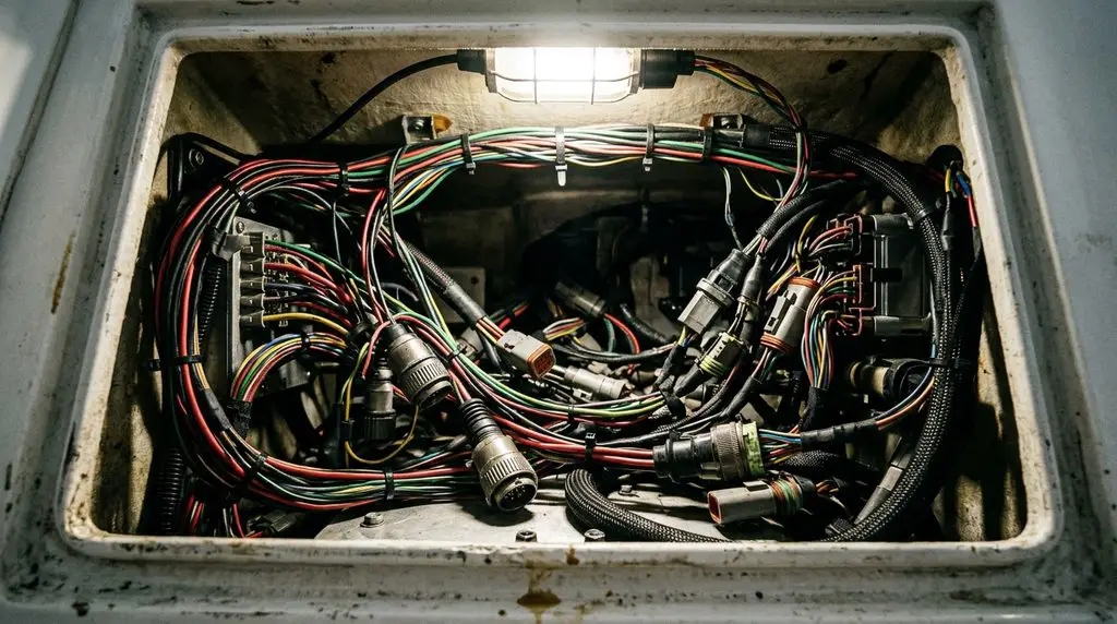
A 2019 39 foot CV with quad Verado 400Rs came in throwing communication codes. Open the rigging tubes on a boat like that and you understand immediately that this isn’t a tighten-the-grounds-and-it’s-fixed situation.
The whole job comes down to one number: 120 ohms. If you understand what the terminator resistors are actually doing and you’re willing to walk the network methodically with a meter, you can find a communication fault on a quad engine dual station setup without guessing and without throwing a $2,500 module at it.
Why It Matters
This is the fault where everybody’s instinct is wrong. A communication code points you at the expensive box, the module, and the standard troubleshooting flow assumes your network is healthy. Follow it and you’ll replace a control module that was never bad.
A CAN network is a line with a terminator at each end telling the data where the network stops. Get that terminator arrangement wrong, or get resistance where it shouldn’t be, and modules that are perfectly fine stop talking to each other.
Understanding the terminators is the entire job.
How The CAN Network Is Laid Out
Here’s the quick version, not a full tutorial.
You’ve got an engine, and a helm with a CCM (command module). The engine harness has terminator resistors on it, 120 ohms each. There are two of them, one with a blue cap and one with a yellow or red cap. That connects to your 14 pin data cable, which runs to the control module harness, which has two more terminators on it, both blue, both 120 ohms.
When one computer talks to another, the signal runs along that network, and the terminators tell it where the end is.
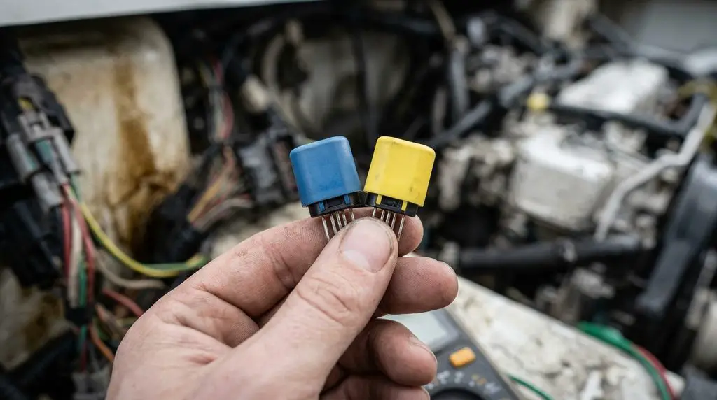
Now add a second helm. You run a white 14 pin harness, another data cable, and another control module harness with its own terminators. The moment you do that, you have to pull the terminators out of the middle. A terminator says “this is the end of the network.” Leave one in the middle and you’ve cut the network in half.
Same thing adding engines. Each additional engine means pulling a terminator and running a jumper to extend the network, so there’s a terminator at each true end and nothing in between.
Two Networks, Not One
This is why there are two terminators at each point. One terminator serves one CAN network, the other serves the second.
CAN 1, also called CAN P for propulsion, is the entire boat.
CAN 2, or CAN H for helm, is the helm-side gear for each engine.
Two separate networks running in parallel, each needing its own correct termination.
Step-By-Step Guide
Set Up For A Resistance Test
Key switches off. Batteries off. This is a resistance test, and voltage on the line will give you garbage readings or damage your meter.
Do not stick meter leads into the pin sockets. You will spread or damage the sockets and create a problem worse than the one you’re chasing. Back-probe or use proper adapters.
Start At The Beginning Of The Network
Go to the engine and unplug the 14 pin harness. You’re starting where a terminator is, because that’s your known reference point.
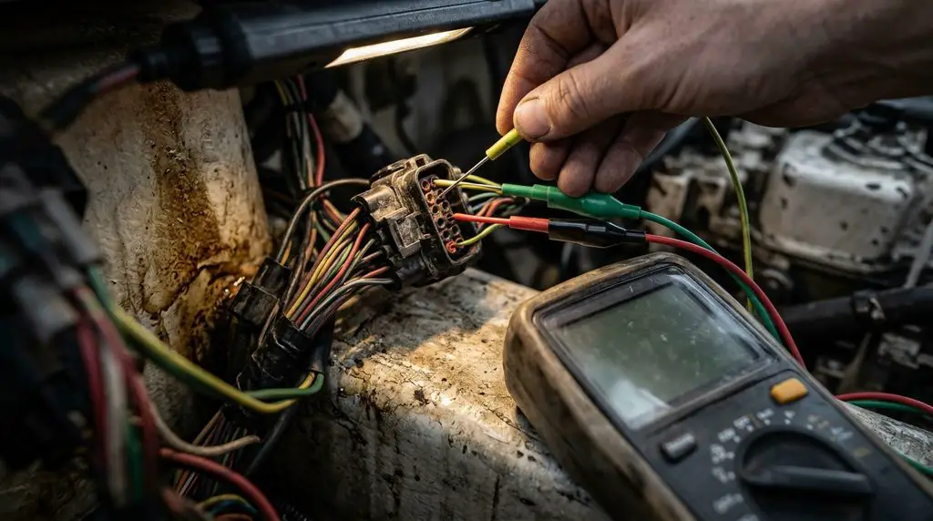
With the meter, check for 120 ohms between the F and G pins for CAN 1 (CAN P, propulsion). Those are white and blue. Then check the pins for CAN 2 (CAN H, helm), which are yellow and brown.
Walk The Network
Go engine to engine, checking the terminator resistance across the network and the resistance at each PCM (propulsion control module) as you go.
The 120 ohm number is what you’re hunting for at every step. Anything meaningfully off tells you where to look.
Isolate By Halves
At the lower station I disconnected the upstairs entirely, just unplugging the 14 pin harnesses going up from the Y harnesses. Then I checked the CCM resistances and the rest of the downstairs network.
With the upper station still disconnected, I plugged the computer in and tested the system with everything on.
Everything downstairs tested clean and worked as it should. That one move told me the problem was upstairs, and cut the search space in half.
Find The Specific Fault
Upstairs, I checked the CCM resistances and looked for 120 ohms the same way.
Then with the computer connected, I plugged in each engine’s 14 pin harness one at a time, watching whether the system misbehaved when each one came online.
The two inside engines were the problem. Those run in what’s called shadow mode, meaning they mimic the outside engines’ throttle. Plugging either of them in would mess up the system.
I changed out the resistor packs, and after that only the port inside engine still gave trouble. New CCM for that engine upstairs, reconfigure the boat, and it was ready to test.
The Optimax Lower Unit, While We’re Here
Separate job the same day. A 2006 225 Optimax on a 25 foot Mako, starboard engine not shifting into gear.
Checked the digital throttle and shift system first by pulling the cowling and shifting into gear, confirming the shift actuator was moving properly. Pulled the boat and checked gear lube. There was a little metal in black gear lube, but nothing out of control, no gray sludge, no heavy metal load.
Pulled the lower unit, confirmed the shift shaft was spinning, then tore into the gear case. Thirteen years in saltwater means nothing wants to come apart. The bearing carrier nut came out with the spanner, then the carrier itself took serious force.
Metal on the reverse gear bearing, and the gear spacer was lodged in the housing. The reverse gear failed, which allowed enough play for the spacer to grind itself into the case.
That engine needs a new lower unit.
Pro Tips
Never probe the front of a pin socket. This is the one that turns a diagnosis into a repair bill. Spread one socket and you’ve introduced an intermittent connection that will haunt that boat for years. Back-probe or use the right adapter.
Disconnect half the system before you measure everything. Unplugging the upper station took the entire second helm out of the equation in about two minutes and proved the downstairs was healthy. That’s faster than testing every point in sequence hoping to stumble on it.
Count your terminators before anything else. Every time an engine or a station gets added to a boat, terminators have to come out of the middle. Somebody adding a second station and leaving a terminator in place is a common, self-inflicted version of this exact fault.
Final Verdict
The understanding is DIY. The repair on a quad engine dual station boat probably isn’t.
If you own a single or twin setup and you’ve got a multimeter, the terminator check is absolutely something you can do. Key off, batteries off, unplug at the engine, look for 120 ohms, and walk it. That alone will find a lot of communication faults and it costs you nothing.
Where it gets past most boat owners is the diagnostic computer. Isolating which of four engines is corrupting the network required plugging them in one at a time with the system live and watching the response. You can’t do that part with a meter.
My honest take: do the resistance work yourself before you call anyone. If you find a terminator in the wrong place or a bad resistor pack, you’ve solved it for the price of a $15 part. If the resistances check out and it’s still throwing codes, now you’ve got something useful to tell the shop, and you’ve saved yourself from paying for a module that was fine.
FAQ
What resistance should a Mercury CAN network read?
120 ohms. Each terminator resistor is 120 ohms, and that’s the number you’re checking for at every point as you walk the network. Key switches and batteries off, since this is a resistance test.
Which pins do I test on a Mercury 14 pin harness?
F and G for CAN 1 (CAN P, propulsion), which are the white and blue wires. The CAN 2 (CAN H, helm) pair is yellow and brown. Never insert leads into the pin sockets themselves.
What is shadow mode on a quad engine setup?
The two inside engines mimic the throttle of the outside engines rather than being controlled independently.
Why do I have to remove terminators when adding an engine or station?
A terminator tells the network where it ends. Adding equipment extends the network, so terminators that were previously at the end are now in the middle and have to come out, or the network is effectively cut there.
Check Us Out!
We hope that this has been insightful and allowed you to understand a little bit more about outboard engine maintenance and what goes into keeping your boat running right.
If you have more questions or want to learn more about your boat and its different systems, consider joining our Boating Academy where we have created HUNDREDS of video courses teaching you basically everything about your boat!
You can also find even more helpful videos on our YouTube channel where we create even more boating videos!
And if you would like to support us to continue bringing you great content, please click the link below to Amazon where we get a commission from anything you are already going to buy! Click Here To Amazon!